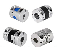
Product Description
GR-40×51 GR Drive Shaft Coupling Flexible Shaft Coupling Flexible Coupling
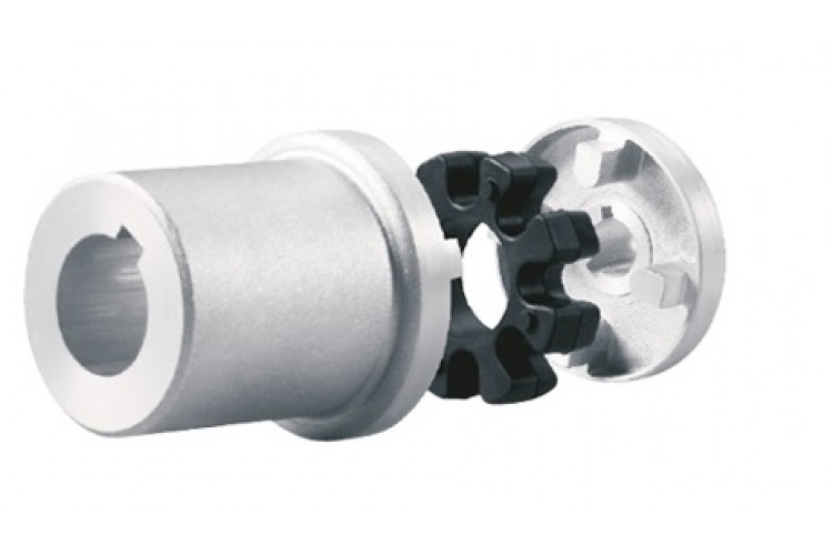
Description of GR-40×51 GR Drive Shaft Coupling Flexible Shaft Coupling Flexible Coupling
>The material is aluminum alloy, and the middle bellows is made of stainless steel with excellent corrosion resistance
>Laser welding is used between bellows and shaft sleeve, with zero rotation clearance, suitable for CHINAMFG and reverse rotation
>Bellows structure can effectively compensate radial, angular and axial deviation
>Designed for servo motor stepper motor
>Fastening method of setscrew
Catalogue of GR-40×51 GR Drive Shaft Coupling Flexible Shaft Coupling Flexible Coupling
|
model parameter |
common bore diameter d1,d2 |
ΦD |
L |
LI |
L2 |
L3 |
N |
F |
tightening screw torque |
|
GR-16×27 |
4,5,6,6.35,7,8 |
16 |
27 |
7.5 |
2 |
8 |
13.5 |
3 |
0.7 |
|
GR-20×32 |
5,6,6.35,7,8,9,9.525,10,11,12 |
20 |
32 |
7.2 |
2.8 |
12 |
18 |
3.5 |
0.7 |
|
GR-22.5×34 |
5,6,6.35,7,8,9,9.525,10,11,12 |
22.5 |
34 |
8.05 |
2.8 |
12.3 |
20.2 |
4.5 |
1.7 |
|
GR-25×37 |
6,6.35,7,8,9,9.525,10,11,12 |
25 |
37 |
9.5 |
3 |
12 |
20.2 |
4.5 |
1.7 |
|
GR-32×42 |
8,9,10,11,12,12.7,14,15 |
32 |
42 |
8 |
4 |
18 |
27.2 |
5.5 |
4 |
|
GR-40×51 |
8,9,9.525,10,11,12,12.7,14,15,16,17,18,19,20 |
40 |
51 |
9.5 |
6 |
20 |
34.5 |
5.5 |
4 |
|
GR-55×57 |
10,11,12,12.7,14,15,16,17,18,19,20,22,24,25 |
55 |
57 |
9 |
6 |
27 |
51.9 |
6.25 |
7 |
|
GR-65×81 |
10,11,12,12.7,14,15,16,17,18,19,20,22,24,25,28,30,32,35,38 |
65 |
81 |
19.5 |
7 |
28 |
60.5 |
8.9 |
7 |
|
model parameter |
Rated torque(N.m) |
allowable eccentricity (mm) |
allowable deflection angle (°) |
allowable axial deviation (mm) |
maximum speed (rpm) |
static torsional stiffness (N.M/rad) |
weight (g) |
|
GR-16×27 |
0.8 |
0.1 |
2 |
-0.8 |
20000 |
150 |
8 |
|
GR-20×32 |
1.5 |
0.1 |
2 |
-1.2 |
18000 |
220 |
13 |
|
GR-22.5×34 |
1.8 |
0.15 |
2 |
-1.2 |
16000 |
300 |
22 |
|
GR-25×37 |
2 |
0.15 |
2 |
-1.2 |
15000 |
330 |
30 |
|
GR-32×42 |
2.5 |
0.2 |
2 |
-1.7 |
11000 |
490 |
53 |
|
GR-40×51 |
6.4 |
0.3 |
2 |
-1.7 |
10000 |
530 |
85 |
|
GR-55×57 |
12 |
0.3 |
2 |
-1.7 |
9000 |
860 |
170 |
|
GR-65×81 |
18 |
0.2 |
2 |
-1.8 |
4500 |
900 |
280 |
/* March 10, 2571 17:59:20 */!function(){function s(e,r){var a,o={};try{e&&e.split(“,”).forEach(function(e,t){e&&(a=e.match(/(.*?):(.*)$/))&&1
What are the Temperature and Speed Limits for Different Drive Coupling Types?
The temperature and speed limits for different drive coupling types vary based on their design, materials, and intended applications. Here are some general guidelines for temperature and speed limits for common drive coupling types:
- Elastomeric Couplings: Elastomeric couplings, which use rubber or elastomer elements, typically have temperature limits ranging from -40°C to 120°C (-40°F to 248°F). The speed limits for elastomeric couplings are generally up to 5000 RPM, but this can vary depending on the coupling size and design.
- Grid Couplings: Grid couplings are designed to handle higher torque and speed requirements. They often have temperature limits between -20°C to 100°C (-4°F to 212°F). The speed limits for grid couplings can range from 5000 to 8000 RPM, depending on the coupling size and grid material.
- Gear Couplings: Gear couplings are known for their high torque capacity and can operate at higher temperatures. Their temperature limits typically range from -20°C to 150°C (-4°F to 302°F). The speed limits for gear couplings can vary widely based on the coupling’s size and design, with some models capable of operating at speeds up to 10,000 RPM or higher.
- Chain Couplings: Chain couplings are suitable for heavy-duty applications. They often have temperature limits between -20°C to 150°C (-4°F to 302°F) depending on the chain material. The speed limits for chain couplings can range from 1500 to 6000 RPM, depending on the chain type and size.
It’s essential to consider the operating environment, load conditions, and coupling material when determining the suitable temperature and speed limits for a specific application. Exceeding the recommended limits can lead to premature wear, reduced performance, and potential coupling failure.
Manufacturers of drive couplings provide detailed specifications and operating guidelines for their products. It’s crucial to consult the manufacturer’s documentation to ensure that the selected coupling is suitable for the intended application and operating conditions.
Can Drive Couplings Compensate for Misalignments in Shafts?
Yes, drive couplings are designed to compensate for certain degrees of misalignment between shafts in mechanical power transmission systems. The ability of a coupling to accommodate misalignments depends on its type and design. Here are the common types of misalignments and the corresponding coupling types that can handle them:
- Parallel Misalignment: This type of misalignment occurs when the axes of the two shafts are parallel but not perfectly aligned. Elastomeric couplings, such as jaw couplings and tire couplings, are commonly used to handle parallel misalignment. These couplings have flexible elements that can offset slight parallel offsets between the shafts.
- Angular Misalignment: Angular misalignment refers to the situation where the axes of the two shafts are not collinear and form an angle. Flexible couplings like beam couplings and Oldham couplings are effective in accommodating angular misalignment. They have a design that allows for relative movement between the shafts while transmitting torque.
- Radial Misalignment: Radial misalignment occurs when there is a gap between the axes of the two shafts. Flexible couplings with multiple elements, such as disc couplings and grid couplings, can handle radial misalignment to some extent. These couplings use flexible components to allow relative movement between the shafts.
- Combination Misalignment: Some couplings, like universal joint couplings and double loop couplings, are designed to compensate for multiple types of misalignments simultaneously. These couplings are suitable for applications where complex misalignments exist.
It’s important to note that while drive couplings can compensate for certain degrees of misalignment, they have their limitations. Excessive misalignment or misalignments beyond their design capabilities can lead to premature wear, reduced coupling life, and decreased efficiency in power transmission. Proper alignment during installation is still essential to ensure the longevity and optimal performance of the coupling and the entire power transmission system.
When selecting a drive coupling for an application with misalignment concerns, it is crucial to consider the type and magnitude of misalignment expected and choose a coupling that can handle it effectively while still meeting other performance requirements.

Types of Drive Couplings and Their Applications in Various Industries
Drive couplings come in various types, each designed to meet specific application requirements. Depending on the industry and the type of machinery involved, different types of drive couplings are used to optimize power transmission efficiency and reliability. Here are some common types of drive couplings and their applications in various industries:
- Jaw Couplings: Jaw couplings are flexible couplings that use elastomeric inserts to transmit torque. They are commonly used in industrial pumps, compressors, and conveyors. The elastomeric inserts provide shock absorption and vibration dampening, making them suitable for applications where misalignment and vibration are present.
- Gear Couplings: Gear couplings are robust and torsionally rigid couplings that use gear teeth to transmit torque between shafts. They are often used in heavy-duty applications such as steel rolling mills, paper mills, and marine propulsion systems. Gear couplings can handle high torque and misalignments, making them ideal for demanding industrial environments.
- Disc Couplings: Disc couplings use thin metal discs to transmit torque and accommodate misalignment. They are widely used in high-speed applications, such as gas turbines, generators, and test rigs. Disc couplings offer high torque capacity and are known for their torsional stiffness and balance characteristics.
- Grid Couplings: Grid couplings use a grid-like flexible element to transmit torque. They are commonly used in industrial pumps, fans, and compressors. Grid couplings offer excellent shock absorption and misalignment capability, making them suitable for applications where protection against sudden shocks is required.
- Tyre Couplings: Tyre couplings use an elastomeric tyre between two hubs to transmit torque. They are widely used in various industries, including steel, mining, and power generation. Tyre couplings can accommodate misalignments and provide vibration damping, making them versatile for different industrial applications.
- Bellows Couplings: Bellows couplings use a thin-walled metallic bellows to transmit torque and compensate for misalignments. They are commonly used in precision motion control applications, such as robotics, CNC machines, and medical equipment, where minimal backlash and high torsional stiffness are required.
- Universal Joints: Universal joints are used to transmit torque between shafts at an angle. They are commonly found in automotive drivelines, agricultural equipment, and industrial machinery. Universal joints allow angular misalignments and are widely used in applications where rotational movement must be transferred through non-aligned shafts.
The choice of drive coupling type depends on factors such as torque requirements, speed, misalignment, and specific environmental conditions. Each type of coupling has its unique advantages and limitations, and selecting the right coupling for a particular application is crucial for ensuring optimal power transmission and machinery performance in various industries.


editor by CX 2024-02-06

