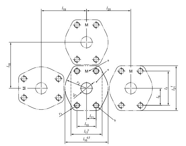
SAE flange dimension chart for code 61 port
May 25, 2019
Sae flange port dimensions port chart has code 61 3000PSI, is the same to ISO 6162-1.

a Letter M to indicate metric type 1 port – raised surface not allowed.
b Four threaded holes of diameter d3 on the port with full thread length l2.
c Minimum flange pad width.
d Recommended flange pad width.
e Maximum surface roughness of port face is ISO 1302-MRR Ramax 3,2.
f Projections within this area can cause interferences
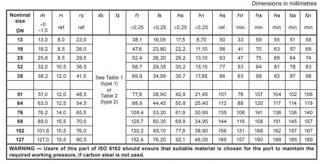
SAE Flange code 61 Port dimensions for flange connections and minimum and recommended flange pad
widths

Nominal
size
DN
d1 r1 r2 d3 l2 l7 l8 l10 l11 l16 l17 l18 l19 l20 l21
+0
–1,5 ref ref ±0,25 ±0,25 ±0,25 ±0,25 ref. min min min min min
13 13,0 8,0 23,0 38,1 19,05 17,5 8,75 50 33 59 55 51 58
19 19,2 8,5 26,0 47,6 23,80 22,2 11,10 56 41 70 63 57 69
25 25,6 8,5 29,5 52,4 26,20 26,2 13,10 63 47 75 69 64 74
32 32,0 10,5 36,5 58,7 29,35 30,2 15,10 77 53 84 81 78 83
38 38,2 12,0 41,5 69,9 34,95 35,7 17,85 86 63 99 93 87 98
51 51,0 12,0 48,5 77,8 38,90 42,9 21,45 101 76 107 104 102 106
64 63,5 12,5 54,5 88,9 44,45 50,8 25,40 113 88 120 117 114 119
76 76,2 14,0 65,5 106,4 53,20 61,9 30,95 135 106 141 138 136 140
89 89,0 15,5 70,0 120,7 60,35 69,9 34,95 144 119 158 151 145 157
102 101,6 15,5 76,0 130,2 65,10 77,8 38,90 156 131 168 162 157 167
127 127,0 15,5 90,5 152,4 76,20 92,1 46,05 185 157 190 188 186 189
WARNING — Users of this part of ISO 6162-1 should ensure that suitable material is chosen for the port to maintain the
required working pressure, if carbon steel is not used.